Project mẫu AVR (phần 2)
19/03/2012
0
2534
13.Pulse period by timer1
- Sơ đồ mạch điện:
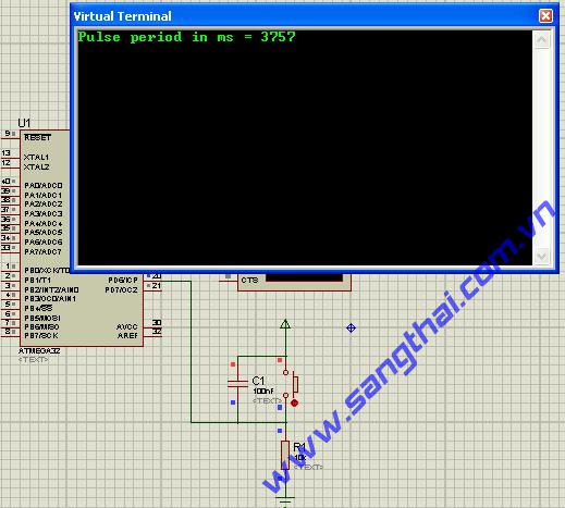
Sơ đồ mạch điện.
- Chương trình mẫu:
Chip type : ATmega32
Program type : Application
Clock frequency : 6.000000 MHz
Memory model : Small
External SRAM size : 0
Data Stack size : 512
*****************************************************/
#include "mega32.h"
// Standard Input/Output functions
#include "stdio.h"
unsigned char ov_counter;
unsigned int starting_edge, ending_edge;
unsigned long clocks;
unsigned int period_out;
bit done = 0;
// Timer 1 overflow interrupt service routine
interrupt [TIM1_OVF] void timer1_ovf_isr(void)
{
// Place your code here
++ov_counter;
}
// Timer 1 input capture interrupt service routine
interrupt [TIM1_CAPT] void timer1_capt_isr(void)
{
// Place your code here
ending_edge = (unsigned int)ICR1H*256 + (unsigned int)ICR1L;
clocks = (unsigned long)ending_edge \
+ ((unsigned long)ov_counter*65536) \
- (unsigned long) starting_edge;
period_out = clocks/750;
done = 1;
ov_counter = 0;
starting_edge = ending_edge;
}
// Declare your global variables here
void main(void)
{
// Declare your local variables here
// Input/Output Ports initialization
// Port A initialization
// Func7=In Func6=In Func5=In Func4=In Func3=In Func2=In Func1=In Func0=In
// State7=T State6=T State5=T State4=T State3=T State2=T State1=T State0=T
PORTA=0x00;
DDRA=0x00;
// Port B initialization
// Func7=In Func6=In Func5=In Func4=In Func3=In Func2=In Func1=In Func0=In
// State7=T State6=T State5=T State4=T State3=T State2=T State1=T State0=T
PORTB=0x00;
DDRB=0x00;
// Port C initialization
// Func7=In Func6=In Func5=In Func4=In Func3=In Func2=In Func1=In Func0=In
// State7=T State6=T State5=T State4=T State3=T State2=T State1=T State0=T
PORTC=0x00;
DDRC=0x00;
// Port D initialization
// Func7=In Func6=In Func5=In Func4=In Func3=In Func2=In Func1=In Func0=In
// State7=T State6=T State5=T State4=T State3=T State2=T State1=T State0=T
PORTD=0x00;
DDRD=0x00;
// Timer/Counter 0 initialization
// Clock source: System Clock
// Clock value: Timer 0 Stopped
// Mode: Normal top=FFh
// OC0 output: Disconnected
TCCR0=0x00;
TCNT0=0x00;
OCR0=0x00;
// Timer/Counter 1 initialization
// Clock source: System Clock
// Clock value: 750.000 kHz
// Mode: Normal top=FFFFh
// OC1A output: Discon.
// OC1B output: Discon.
// Noise Canceler: Off
// Input Capture on Rising Edge
// Timer 1 Overflow Interrupt: On
// Input Capture Interrupt: On
// Compare A Match Interrupt: Off
// Compare B Match Interrupt: Off
TCCR1A=0x00;
TCCR1B=0x42;
TCNT1H=0x00;
TCNT1L=0x00;
ICR1H=0x00;
ICR1L=0x00;
OCR1AH=0x00;
OCR1AL=0x00;
OCR1BH=0x00;
OCR1BL=0x00;
// Timer/Counter 2 initialization
// Clock source: System Clock
// Clock value: Timer 2 Stopped
// Mode: Normal top=FFh
// OC2 output: Disconnected
ASSR=0x00;
TCCR2=0x00;
TCNT2=0x00;
OCR2=0x00;
// External Interrupt(s) initialization
// INT0: Off
// INT1: Off
// INT2: Off
MCUCR=0x00;
MCUCSR=0x00;
// Timer(s)/Counter(s) Interrupt(s) initialization
TIMSK=0x24;
// USART initialization
// Communication Parameters: 8 Data, 1 Stop, No Parity
// USART Receiver: On
// USART Transmitter: On
// USART Mode: Asynchronous
// USART Baud rate: 9600
UCSRA=0x00;
UCSRB=0x18;
UCSRC=0x86;
UBRRH=0x00;
UBRRL=0x26;
// Analog Comparator initialization
// Analog Comparator: Off
// Analog Comparator Input Capture by Timer/Counter 1: Off
ACSR=0x80;
SFIOR=0x00;
// Global enable interrupts
#asm("sei")
while (1)
{
if(done){
printf("Pulse period in ms = %u\n\r", period_out);
done = 0;
}
};
}
14.ADC_Complete_Int.
- Sơ đồ mạch điện:
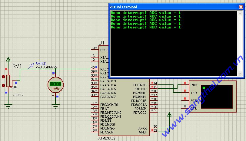
Sơ đồ mạch điện.
- Chương trình mẫu:
Chip type : ATmega32
Program type : Application
Clock frequency : 7.372800 MHz
Memory model : Small
External SRAM size : 0
Data Stack size : 512
*****************************************************/
#include "mega32.h"
#include "delay.h"
// Standard Input/Output functions
#include"stdio.h"
#define ADC_VREF_TYPE 0x00
// Declare your global variables here
bit adc_done = 0; // Global ADC done flag bit
// ADC interrupt service routine
interrupt [ADC_INT] void adc_isr(void)
{
unsigned int adc_result;
// Read the AD conversion result
adc_result = ADCW;
// Always clear ADC IF bit
ADCSRA |= 0x10;
// print this value
printf("Done interrupt! ADC value = %d\n\r",adc_result);
// Set done bit
adc_done = 1;
}
// Trigger ADC conversion
void adc_trigger_conv(unsigned char adc_input)
{
// Clear done bit
adc_done = 0;
// Select adc channel
ADMUX=adc_input|ADC_VREF_TYPE;
// Start the AD conversion
ADCSRA|=0x40;
// Don't wait for complete, exist now.
}
void main(void)
{
// Declare your local variables here
// Input/Output Ports initialization
// Port A initialization
// Func7=In Func6=In Func5=In Func4=In Func3=In Func2=In Func1=In Func0=In
// State7=T State6=T State5=T State4=T State3=T State2=T State1=T State0=T
PORTA=0x00;
DDRA=0x00;
// Port B initialization
// Func7=In Func6=In Func5=In Func4=In Func3=In Func2=In Func1=In Func0=In
// State7=T State6=T State5=T State4=T State3=T State2=T State1=T State0=T
PORTB=0x00;
DDRB=0x00;
// Port C initialization
// Func7=In Func6=In Func5=In Func4=In Func3=In Func2=In Func1=In Func0=In
// State7=T State6=T State5=T State4=T State3=T State2=T State1=T State0=T
PORTC=0x00;
DDRC=0x00;
// Port D initialization
// Func7=In Func6=In Func5=In Func4=In Func3=In Func2=In Func1=In Func0=In
// State7=T State6=T State5=T State4=T State3=T State2=T State1=T State0=T
PORTD=0x00;
DDRD=0x00;
// Timer/Counter 0 initialization
// Clock source: System Clock
// Clock value: Timer 0 Stopped
// Mode: Normal top=FFh
// OC0 output: Disconnected
TCCR0=0x00;
TCNT0=0x00;
OCR0=0x00;
// Timer/Counter 1 initialization
// Clock source: System Clock
// Clock value: Timer 1 Stopped
// Mode: Normal top=FFFFh
// OC1A output: Discon.
// OC1B output: Discon.
// Noise Canceler: Off
// Input Capture on Falling Edge
// Timer 1 Overflow Interrupt: Off
// Input Capture Interrupt: Off
// Compare A Match Interrupt: Off
// Compare B Match Interrupt: Off
TCCR1A=0x00;
TCCR1B=0x00;
TCNT1H=0x00;
TCNT1L=0x00;
ICR1H=0x00;
ICR1L=0x00;
OCR1AH=0x00;
OCR1AL=0x00;
OCR1BH=0x00;
OCR1BL=0x00;
// Timer/Counter 2 initialization
// Clock source: System Clock
// Clock value: Timer 2 Stopped
// Mode: Normal top=FFh
// OC2 output: Disconnected
ASSR=0x00;
TCCR2=0x00;
TCNT2=0x00;
OCR2=0x00;
// External Interrupt(s) initialization
// INT0: Off
// INT1: Off
// INT2: Off
MCUCR=0x00;
MCUCSR=0x00;
// Timer(s)/Counter(s) Interrupt(s) initialization
TIMSK=0x00;
// USART initialization
// Communication Parameters: 8 Data, 1 Stop, No Parity
// USART Receiver: On
// USART Transmitter: On
// USART Mode: Asynchronous
// USART Baud rate: 9600
UCSRA=0x00;
UCSRB=0x18;
UCSRC=0x86;
UBRRH=0x00;
UBRRL=0x2F;
// Analog Comparator initialization
// Analog Comparator: Off
// Analog Comparator Input Capture by Timer/Counter 1: Off
ACSR=0x80;
SFIOR=0x00;
// ADC initialization
// ADC Clock frequency: 115.200 kHz
// ADC Voltage Reference: AREF pin
ADMUX=ADC_VREF_TYPE;
ADCSRA=0x8E;
// Global enable interrupts
#asm("sei")
// trigger for the first time
adc_trigger_conv(0);
while (1)
{
// Place your code here
if (adc_done) adc_trigger_conv(0);
delay_ms(1000);
};
}
15.ADC_Differential.
- Sơ đồ mạch điện:
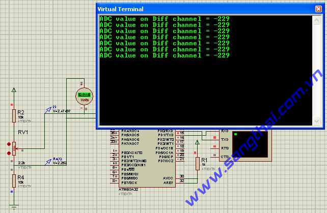
Sơ đồ mạch điện.
- Chương trình mẫu:
Chip type : ATmega32
Program type : Application
Clock frequency : 7.372800 MHz
Memory model : Small
External SRAM size : 0
Data Stack size : 512
*****************************************************/
#include "mega32.h"
#include "delay.h"
// Standard Input/Output functions
#include "stdio.h"
#define ADC_VREF_TYPE 0x00
// User's defines
// Here, we choose ADC0 as Neg Input
// ADC1 as Pos Input
// Gain set to 10x
// Look up on table in datasheet --> MUX4:0 = 0b01001
#define ADC_DIFF_TYPE (0b01001)
// Convert value from ADC data register with its sign (+/-)
int convert_adc_value(unsigned int adc_10bit_input_value)
{
int result;
result = (int)(adc_10bit_input_value & 0x1FF);
result = (adc_10bit_input_value & (1 << 9)) ? (-(512 - result)) : result;
return result;
}
// Read the AD conversion result
int read_diff_adc(void)
{
ADMUX = ADC_VREF_TYPE | ADC_DIFF_TYPE;
// Start the AD conversion
ADCSRA|=0x40;
// Wait for the AD conversion to complete
while ((ADCSRA & 0x10)==0);
ADCSRA|=0x10;
return ADCW;
}
// Declare your global variables here
void main(void)
{
// Declare your local variables here
unsigned int u16_adc;
int s16_adc;
// Input/Output Ports initialization
// Port A initialization
// Func7=In Func6=In Func5=In Func4=In Func3=In Func2=In Func1=In Func0=In
// State7=T State6=T State5=T State4=T State3=T State2=T State1=T State0=T
PORTA=0x00;
DDRA=0x00;
// Port B initialization
// Func7=In Func6=In Func5=In Func4=In Func3=In Func2=In Func1=In Func0=In
// State7=T State6=T State5=T State4=T State3=T State2=T State1=T State0=T
PORTB=0x00;
DDRB=0x00;
// Port C initialization
// Func7=In Func6=In Func5=In Func4=In Func3=In Func2=In Func1=In Func0=In
// State7=T State6=T State5=T State4=T State3=T State2=T State1=T State0=T
PORTC=0x00;
DDRC=0x00;
// Port D initialization
// Func7=In Func6=In Func5=In Func4=In Func3=In Func2=In Func1=In Func0=In
// State7=T State6=T State5=T State4=T State3=T State2=T State1=T State0=T
PORTD=0x00;
DDRD=0x00;
// Timer/Counter 0 initialization
// Clock source: System Clock
// Clock value: Timer 0 Stopped
// Mode: Normal top=FFh
// OC0 output: Disconnected
TCCR0=0x00;
TCNT0=0x00;
OCR0=0x00;
// Timer/Counter 1 initialization
// Clock source: System Clock
// Clock value: Timer 1 Stopped
// Mode: Normal top=FFFFh
// OC1A output: Discon.
// OC1B output: Discon.
// Noise Canceler: Off
// Input Capture on Falling Edge
// Timer 1 Overflow Interrupt: Off
// Input Capture Interrupt: Off
// Compare A Match Interrupt: Off
// Compare B Match Interrupt: Off
TCCR1A=0x00;
TCCR1B=0x00;
TCNT1H=0x00;
TCNT1L=0x00;
ICR1H=0x00;
ICR1L=0x00;
OCR1AH=0x00;
OCR1AL=0x00;
OCR1BH=0x00;
OCR1BL=0x00;
// Timer/Counter 2 initialization
// Clock source: System Clock
// Clock value: Timer 2 Stopped
// Mode: Normal top=FFh
// OC2 output: Disconnected
ASSR=0x00;
TCCR2=0x00;
TCNT2=0x00;
OCR2=0x00;
// External Interrupt(s) initialization
// INT0: Off
// INT1: Off
// INT2: Off
MCUCR=0x00;
MCUCSR=0x00;
// Timer(s)/Counter(s) Interrupt(s) initialization
TIMSK=0x00;
// USART initialization
// Communication Parameters: 8 Data, 1 Stop, No Parity
// USART Receiver: On
// USART Transmitter: On
// USART Mode: Asynchronous
// USART Baud rate: 9600
UCSRA=0x00;
UCSRB=0x18;
UCSRC=0x86;
UBRRH=0x00;
UBRRL=0x2F;
// Analog Comparator initialization
// Analog Comparator: Off
// Analog Comparator Input Capture by Timer/Counter 1: Off
ACSR=0x80;
SFIOR=0x00;
// ADC initialization
// ADC Clock frequency: 115.200 kHz
// ADC Voltage Reference: AREF pin
ADMUX=ADC_VREF_TYPE;
ADCSRA=0x86;
while (1)
{
// Get adc value from ADC register
u16_adc = read_diff_adc();
// Convert to signed int value
s16_adc = convert_adc_value(u16_adc);
printf("ADC value on Diff channel = %d \n\r", s16_adc);
delay_ms(1000);
};
}
16.ADC_Trigger_By_Int.
- Sơ đồ mạch điện:
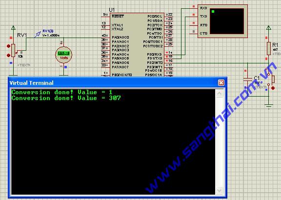
Sơ đồ mạch điện.
- Chương trình mẫu:
Chip type : ATmega32
Program type : Application
Clock frequency : 7.372800 MHz
Memory model : Small
External SRAM size : 0
Data Stack size : 512
*****************************************************/
#include "mega32.h"
// Standard Input/Output functions
#include "stdio.h"
// User's definitions -------------------------------
// ADSRA register definitions
#define ADEN (1 << 7) // ADC Enable
#define ADSC (1 << 6) // ADC Start Conversion
#define ADATE (1 << 5) // ADC Auto Trigger Enable
#define ADIF (1 << 4) // ADC Interrupt Flag
#define ADIE (1 << 3) // ADC Interrupt Enable
#define ADPS2 (1 << 2) // ADC Prescale bit 2
#define ADPS1 (1 << 1) // ADC Prescale bit 1
#define ADPS0 (1) // ADC Prescale bit 0
// SFIOR register definitions
#define ADTS2 (1 << 7) // ADC Trigger Source bit 2
#define ADTS1 (1 << 6) // ADC Trigger Source bit 1
#define ADTS0 (1 << 5) // ADC Trigger Source bit 0
#define ADTS_MASK (ADTS2 | ADTS1 | ADTS0) // ADC Trigger Source Bits Mask
// GIFR register definitions
#define INT0 (1 << 6) // INT0
#define ADC_VREF_TYPE 0x00
// Global varables -------------------------------
// ADC interrupt service routine
interrupt [ADC_INT] void adc_isr(void)
{
unsigned int adc_data;
// Read the AD conversion result
adc_data=ADCW;
// Place your code here
printf("Conversion done! Value = %d\n\r",adc_data);
// Clear INT0 flag for next auto trigger by INT0
GIFR = INT0;
}
// Configure ADC channel that conversion will be trigger to
// convert ADC for.
void config_adc_channel(unsigned char adc_input)
{
ADMUX=adc_input|ADC_VREF_TYPE;
}
void main(void)
{
// Declare your local variables here
unsigned char temp;
// Input/Output Ports initialization
// Port A initialization
// Func7=In Func6=In Func5=In Func4=In Func3=In Func2=In Func1=In Func0=In
// State7=T State6=T State5=T State4=T State3=T State2=T State1=T State0=T
PORTA=0x00;
DDRA=0x00;
// Port B initialization
// Func7=In Func6=In Func5=In Func4=In Func3=In Func2=In Func1=In Func0=In
// State7=T State6=T State5=T State4=T State3=T State2=T State1=T State0=T
PORTB=0x00;
DDRB=0x00;
// Port C initialization
// Func7=In Func6=In Func5=In Func4=In Func3=In Func2=In Func1=In Func0=In
// State7=T State6=T State5=T State4=T State3=T State2=T State1=T State0=T
PORTC=0x00;
DDRC=0x00;
// Port D initialization
// Func7=In Func6=In Func5=In Func4=In Func3=In Func2=In Func1=In Func0=In
// State7=T State6=T State5=T State4=T State3=T State2=T State1=T State0=T
PORTD=0x00;
DDRD=0x00;
// Timer/Counter 0 initialization
// Clock source: System Clock
// Clock value: Timer 0 Stopped
// Mode: Normal top=FFh
// OC0 output: Disconnected
TCCR0=0x00;
TCNT0=0x00;
OCR0=0x00;
// Timer/Counter 1 initialization
// Clock source: System Clock
// Clock value: Timer 1 Stopped
// Mode: Normal top=FFFFh
// OC1A output: Discon.
// OC1B output: Discon.
// Noise Canceler: Off
// Input Capture on Falling Edge
// Timer 1 Overflow Interrupt: Off
// Input Capture Interrupt: Off
// Compare A Match Interrupt: Off
// Compare B Match Interrupt: Off
TCCR1A=0x00;
TCCR1B=0x00;
TCNT1H=0x00;
TCNT1L=0x00;
ICR1H=0x00;
ICR1L=0x00;
OCR1AH=0x00;
OCR1AL=0x00;
OCR1BH=0x00;
OCR1BL=0x00;
// Timer/Counter 2 initialization
// Clock source: System Clock
// Clock value: Timer 2 Stopped
// Mode: Normal top=FFh
// OC2 output: Disconnected
ASSR=0x00;
TCCR2=0x00;
TCNT2=0x00;
OCR2=0x00;
// External Interrupt(s) initialization
// INT0: On
// INT0 Mode: Falling Edge
// INT1: Off
// INT2: Off
GICR=0x00; // Disable INT0 Request to Global Interrupt
MCUCR=0x02; // Falling Edge on INT0
MCUCSR=0x00;
GIFR=0x40; // Clear INT0 Interrupt Flag
// Timer(s)/Counter(s) Interrupt(s) initialization
TIMSK=0x00;
// USART initialization
// Communication Parameters: 8 Data, 1 Stop, No Parity
// USART Receiver: On
// USART Transmitter: On
// USART Mode: Asynchronous
// USART Baud rate: 9600
UCSRA=0x00;
UCSRB=0x18;
UCSRC=0x86;
UBRRH=0x00;
UBRRL=0x2F;
// Analog Comparator initialization
// Analog Comparator: Off
// Analog Comparator Input Capture by Timer/Counter 1: Off
ACSR=0x80;
SFIOR=0x00;
// ADC initialization
// ADC Clock frequency: 115.200 kHz
// ADC Voltage Reference: AREF pin
ADMUX=ADC_VREF_TYPE;
// Enable Auto trigger conversion --------------------------------
ADCSRA = 0x8E | ADATE;
// Configure trigger source --------------------------------------
// Read out and mask ADTS[2..0] bit in the current status of SFIOR
temp = SFIOR & (~(ADTS_MASK));
// Choose External Interrupt 0 (see datasheet)
temp |= ADTS1;
// Write back to SFIOR
SFIOR = temp;
// Must configure ADC channel before using
config_adc_channel(0);
// Global enable interrupts
#asm("sei")
while (1)
{
// Place your code here
};
}
17.ADC_using_LM35.
- Sơ đồ mạch điện:
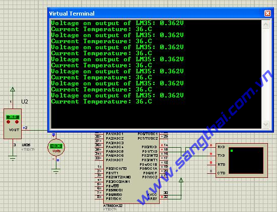
Sơ đồ mạch điện.
- Chương trình mẫu:
Chip type : ATmega32
Program type : Application
Clock frequency : 7.372800 MHz
Memory model : Small
External SRAM size : 0
Data Stack size : 512
*****************************************************/
#include "mega32.h"
#include "delay.h"
#include "stdio.h"
// Standard Input/Output functions
#include "stdlib.h"
#define ADC_VREF_TYPE 0x00
// Read the AD conversion result
unsigned int read_adc(unsigned char adc_input)
{
ADMUX=adc_input|ADC_VREF_TYPE;
// Start the AD conversion
ADCSRA|=0x40;
// Wait for the AD conversion to complete
while ((ADCSRA & 0x10)==0);
ADCSRA|=0x10;
return ADCW;
}
// Declare your global variables here
void main(void)
{
// Declare your local variables here
unsigned int adc_value; // ADC result
float lm35_voltage; // Voltage on Output of LM35
unsigned int lm35_temp; // Current temperature
char buff[10]; // temp buff hold conversion from float number to string
// Input/Output Ports initialization
// Port A initialization
// Func7=In Func6=In Func5=In Func4=In Func3=In Func2=In Func1=In Func0=In
// State7=T State6=T State5=T State4=T State3=T State2=T State1=T State0=T
PORTA=0x00;
DDRA=0x00;
// Port B initialization
// Func7=In Func6=In Func5=In Func4=In Func3=In Func2=In Func1=In Func0=In
// State7=T State6=T State5=T State4=T State3=T State2=T State1=T State0=T
PORTB=0x00;
DDRB=0x00;
// Port C initialization
// Func7=In Func6=In Func5=In Func4=In Func3=In Func2=In Func1=In Func0=In
// State7=T State6=T State5=T State4=T State3=T State2=T State1=T State0=T
PORTC=0x00;
DDRC=0x00;
// Port D initialization
// Func7=In Func6=In Func5=In Func4=In Func3=In Func2=In Func1=In Func0=In
// State7=T State6=T State5=T State4=T State3=T State2=T State1=T State0=T
PORTD=0x00;
DDRD=0x00;
// Timer/Counter 0 initialization
// Clock source: System Clock
// Clock value: Timer 0 Stopped
// Mode: Normal top=FFh
// OC0 output: Disconnected
TCCR0=0x00;
TCNT0=0x00;
OCR0=0x00;
// Timer/Counter 1 initialization
// Clock source: System Clock
// Clock value: Timer 1 Stopped
// Mode: Normal top=FFFFh
// OC1A output: Discon.
// OC1B output: Discon.
// Noise Canceler: Off
// Input Capture on Falling Edge
// Timer 1 Overflow Interrupt: Off
// Input Capture Interrupt: Off
// Compare A Match Interrupt: Off
// Compare B Match Interrupt: Off
TCCR1A=0x00;
TCCR1B=0x00;
TCNT1H=0x00;
TCNT1L=0x00;
ICR1H=0x00;
ICR1L=0x00;
OCR1AH=0x00;
OCR1AL=0x00;
OCR1BH=0x00;
OCR1BL=0x00;
// Timer/Counter 2 initialization
// Clock source: System Clock
// Clock value: Timer 2 Stopped
// Mode: Normal top=FFh
// OC2 output: Disconnected
ASSR=0x00;
TCCR2=0x00;
TCNT2=0x00;
OCR2=0x00;
// External Interrupt(s) initialization
// INT0: Off
// INT1: Off
// INT2: Off
MCUCR=0x00;
MCUCSR=0x00;
// Timer(s)/Counter(s) Interrupt(s) initialization
TIMSK=0x00;
// USART initialization
// Communication Parameters: 8 Data, 1 Stop, No Parity
// USART Receiver: On
// USART Transmitter: On
// USART Mode: Asynchronous
// USART Baud rate: 9600
UCSRA=0x00;
UCSRB=0x18;
UCSRC=0x86;
UBRRH=0x00;
UBRRL=0x2F;
// Analog Comparator initialization
// Analog Comparator: Off
// Analog Comparator Input Capture by Timer/Counter 1: Off
ACSR=0x80;
SFIOR=0x00;
// ADC initialization
// ADC Clock frequency: 115.200 kHz
// ADC Voltage Reference: AREF pin
ADMUX=ADC_VREF_TYPE;
ADCSRA=0x86;
while (1)
{
// Get ADC value
adc_value = read_adc(0);
// Calc to voltage value
lm35_voltage = (float)adc_value*5/1023;
ftoa(lm35_voltage,3,buff);
printf("Voltage on output of LM35: %sV\n\r",buff);
// Calc to temperature - note that LM35 has Linear +10.0 mV/C scale factor
lm35_temp = (unsigned int)((float)adc_value*500/1023 + 0.5);
printf("Current Temperature: %d.C\n\r",lm35_temp);
delay_ms(2000);
};
}
18.ADC_using_VR.
- Sơ đồ mạch điện:
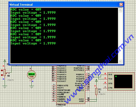
Sơ đồ mạch điện.
- Chương trình mẫu:
Chip type : ATmega32
Program type : Application
Clock frequency : 7.372800 MHz
Memory model : Small
External SRAM size : 0
Data Stack size : 512
*****************************************************/
#include "mega32.h"
// Standard Input/Output functions
#include "delay.h"
#include "stdio.h"
#include "stdlib.h"
#define ADC_VREF_TYPE 0x00
// Read the AD conversion result
unsigned int read_adc(unsigned char adc_input)
{
ADMUX=adc_input|ADC_VREF_TYPE;
// Start the AD conversion
ADCSRA|=0x40;
// Wait for the AD conversion to complete
while ((ADCSRA & 0x10)==0);
ADCSRA|=0x10;
return ADCW;
}
// Declare your global variables here
unsigned int adc_value;
float input_voltage;
void main(void)
{
// Declare your local variables here
char buff[10];
// Input/Output Ports initialization
// Port A initialization
// Func7=In Func6=In Func5=In Func4=In Func3=In Func2=In Func1=In Func0=In
// State7=T State6=T State5=T State4=T State3=T State2=T State1=T State0=T
PORTA=0x00;
DDRA=0x00;
// Port B initialization
// Func7=In Func6=In Func5=In Func4=In Func3=In Func2=In Func1=In Func0=In
// State7=T State6=T State5=T State4=T State3=T State2=T State1=T State0=T
PORTB=0x00;
DDRB=0x00;
// Port C initialization
// Func7=In Func6=In Func5=In Func4=In Func3=In Func2=In Func1=In Func0=In
// State7=T State6=T State5=T State4=T State3=T State2=T State1=T State0=T
PORTC=0x00;
DDRC=0x00;
// Port D initialization
// Func7=In Func6=In Func5=In Func4=In Func3=In Func2=In Func1=In Func0=In
// State7=T State6=T State5=T State4=T State3=T State2=T State1=T State0=T
PORTD=0x00;
DDRD=0x00;
// Timer/Counter 0 initialization
// Clock source: System Clock
// Clock value: Timer 0 Stopped
// Mode: Normal top=FFh
// OC0 output: Disconnected
TCCR0=0x00;
TCNT0=0x00;
OCR0=0x00;
// Timer/Counter 1 initialization
// Clock source: System Clock
// Clock value: Timer 1 Stopped
// Mode: Normal top=FFFFh
// OC1A output: Discon.
// OC1B output: Discon.
// Noise Canceler: Off
// Input Capture on Falling Edge
// Timer 1 Overflow Interrupt: Off
// Input Capture Interrupt: Off
// Compare A Match Interrupt: Off
// Compare B Match Interrupt: Off
TCCR1A=0x00;
TCCR1B=0x00;
TCNT1H=0x00;
TCNT1L=0x00;
ICR1H=0x00;
ICR1L=0x00;
OCR1AH=0x00;
OCR1AL=0x00;
OCR1BH=0x00;
OCR1BL=0x00;
// Timer/Counter 2 initialization
// Clock source: System Clock
// Clock value: Timer 2 Stopped
// Mode: Normal top=FFh
// OC2 output: Disconnected
ASSR=0x00;
TCCR2=0x00;
TCNT2=0x00;
OCR2=0x00;
// External Interrupt(s) initialization
// INT0: Off
// INT1: Off
// INT2: Off
MCUCR=0x00;
MCUCSR=0x00;
// Timer(s)/Counter(s) Interrupt(s) initialization
TIMSK=0x00;
// USART initialization
// Communication Parameters: 8 Data, 1 Stop, No Parity
// USART Receiver: On
// USART Transmitter: On
// USART Mode: Asynchronous
// USART Baud rate: 9600
UCSRA=0x00;
UCSRB=0x18;
UCSRC=0x86;
UBRRH=0x00;
UBRRL=0x2F;
// Analog Comparator initialization
// Analog Comparator: Off
// Analog Comparator Input Capture by Timer/Counter 1: Off
ACSR=0x80;
SFIOR=0x00;
// ADC initialization
// ADC Clock frequency: 115.200 kHz
// ADC Voltage Reference: AREF pin
ADMUX=ADC_VREF_TYPE;
ADCSRA=0x86;
while (1)
{
adc_value = read_adc(0);
printf("ADC value = %d\n\r",adc_value);
input_voltage = ((float)adc_value*5)/1023;
ftoa(input_voltage, 3, buff);
printf("Input voltage = %sV\n\r", buff);
delay_ms(1000);
};
}
19.ADC_using_AVR_LEDbar.
- Sơ đồ mạch điện:
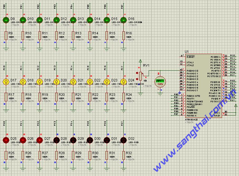
Sơ đồ mạch điện.
- Chương trình mẫu:
Chip type : ATmega32
Program type : Application
Clock frequency : 7.372800 MHz
Memory model : Small
External SRAM size : 0
Data Stack size : 512
*****************************************************/
#include "mega32.h"
#include "delay.h"
#define ADC_VREF_TYPE 0x00
// Read the AD conversion result
unsigned int read_adc(unsigned char adc_input)
{
ADMUX=adc_input|ADC_VREF_TYPE;
// Start the AD conversion
ADCSRA|=0x40;
// Wait for the AD conversion to complete
while ((ADCSRA & 0x10)==0);
ADCSRA|=0x10;
return ADCW;
}
// Declare your global variables here
void main(void)
{
// Declare your local variables here
unsigned int vr_value; // ADC result of voltage getting from VR.
unsigned long int led_bar_value; // Temp led bar value after calculating.
// Input/Output Ports initialization
// Port A initialization
// Func7=In Func6=In Func5=In Func4=In Func3=In Func2=In Func1=In Func0=In
// State7=T State6=T State5=T State4=T State3=T State2=T State1=T State0=T
PORTA=0x00;
DDRA=0x00;
// Port B initialization
// Func7=Out Func6=Out Func5=Out Func4=Out Func3=Out Func2=Out Func1=Out Func0=Out
// State7=0 State6=0 State5=0 State4=0 State3=0 State2=0 State1=0 State0=0
PORTB=0x00;
DDRB=0xFF;
// Port C initialization
// Func7=Out Func6=Out Func5=Out Func4=Out Func3=Out Func2=Out Func1=Out Func0=Out
// State7=0 State6=0 State5=0 State4=0 State3=0 State2=0 State1=0 State0=0
PORTC=0x00;
DDRC=0xFF;
// Port D initialization
// Func7=Out Func6=Out Func5=Out Func4=Out Func3=Out Func2=Out Func1=Out Func0=Out
// State7=0 State6=0 State5=0 State4=0 State3=0 State2=0 State1=0 State0=0
PORTD=0x00;
DDRD=0xFF;
// Timer/Counter 0 initialization
// Clock source: System Clock
// Clock value: Timer 0 Stopped
// Mode: Normal top=FFh
// OC0 output: Disconnected
TCCR0=0x00;
TCNT0=0x00;
OCR0=0x00;
// Timer/Counter 1 initialization
// Clock source: System Clock
// Clock value: Timer 1 Stopped
// Mode: Normal top=FFFFh
// OC1A output: Discon.
// OC1B output: Discon.
// Noise Canceler: Off
// Input Capture on Falling Edge
// Timer 1 Overflow Interrupt: Off
// Input Capture Interrupt: Off
// Compare A Match Interrupt: Off
// Compare B Match Interrupt: Off
TCCR1A=0x00;
TCCR1B=0x00;
TCNT1H=0x00;
TCNT1L=0x00;
ICR1H=0x00;
ICR1L=0x00;
OCR1AH=0x00;
OCR1AL=0x00;
OCR1BH=0x00;
OCR1BL=0x00;
// Timer/Counter 2 initialization
// Clock source: System Clock
// Clock value: Timer 2 Stopped
// Mode: Normal top=FFh
// OC2 output: Disconnected
ASSR=0x00;
TCCR2=0x00;
TCNT2=0x00;
OCR2=0x00;
// External Interrupt(s) initialization
// INT0: Off
// INT1: Off
// INT2: Off
MCUCR=0x00;
MCUCSR=0x00;
// Timer(s)/Counter(s) Interrupt(s) initialization
TIMSK=0x00;
// Analog Comparator initialization
// Analog Comparator: Off
// Analog Comparator Input Capture by Timer/Counter 1: Off
ACSR=0x80;
SFIOR=0x00;
// ADC initialization
// ADC Clock frequency: 115.200 kHz
// ADC Voltage Reference: AREF pin
ADMUX=ADC_VREF_TYPE;
ADCSRA=0x86;
while (1)
{
// Get ADC value on VR - it's connected to ADC0
vr_value = read_adc(0);
// Here, we have 24 leds, so we assume 24 steps or 24 level.
// Note that, the result is always be rounded DOWN, so 0.5 is added to this result.
vr_value = (unsigned int)(((float)vr_value * 24) / 1023 + 0.5);
// we must fill '1' value from 0 to current step
led_bar_value = (1 << ((unsigned long int)vr_value)) - 1;
// Send each byte of this value to each port
PORTB = led_bar_value & 0xFF;
PORTC = (led_bar_value >> 8) & 0xFF;
PORTD = (led_bar_value >> 16) & 0xFF;
// Delay for a while
delay_ms(100);
};
}
20.TWI_I2C_AT24C1024.
- Sơ đồ mạch điện:
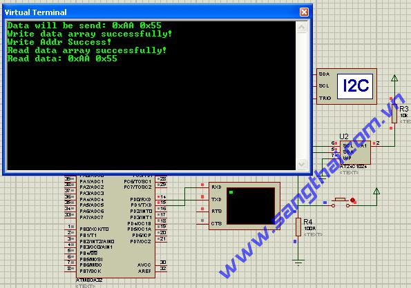
Sơ đồ mạch điện.
- Chương trình mẫu:
Chip type : ATmega32
Program type : Application
Clock frequency : 7.372800 MHz
Memory model : Small
External SRAM size : 0
Data Stack size : 512
*****************************************************/
#include "mega32.h"
// Standard Input/Output functions
#include "stdio.h"
// User's defines
// TWCR definitions
#define TWINT (1 << 7)
#define TWEA (1 << 6)
#define TWSTA (1 << 5)
#define TWSTO (1 << 4)
#define TWWC (1 << 3)
#define TWEN (1 << 2)
#define TWIE (1)
// macro used to get TWI return status code
#define TWI_STATUS (TWSR & 0xF8)
// macro used to check int flag
#define TWI_FLAG (TWCR & TWINT)
// Status code defines
// MT mode
#define MT_START 0x08
#define MT_REPEATSTART 0x10
#define MT_SLA_W_ACK 0x18
#define MT_SLA_W_NACK 0x20
#define MT_DATA_ACK 0x28
#define MT_DATA_NACK 0x30
// MR mode
#define MR_START 0x08
#define MR_REPEATSTART 0x10
#define MR_SLA_R_ACK 0x40
#define MR_SLA_R_NACK 0x48
#define MR_DATA_ACK 0x50
#define MR_DATA_NACK 0x58
// Return status defines
#define OK (0)
#define ERROR (1)
// EEPROM Device Address define - 0b10100A1P0
// In this case, A1 is pulled high, so EEPROM Address is (0b10100100 | (P0<
// See Datasheet for more details
#define EEPROM_ADDR (0b10100100)
// EEPROM Page Address define
#define P0_0 (0)
#define P0_1 (1<
unsigned char TWI_SendStart(void)
{
TWCR = TWEN | TWSTA | TWINT;
while(TWI_FLAG == 0);
return TWI_STATUS;
}
unsigned char TWI_WriteData(unsigned char data)
{
// write value to TWDR
TWDR = data;
TWCR = TWEN | TWINT;
while(TWI_FLAG == 0);
return TWI_STATUS;
}
unsigned char TWI_ReadData(unsigned char *data, unsigned char ack)
{
if (ack){
// return ack for next receive
TWCR = TWEN | TWEA | TWINT;
} else {
// return nack
TWCR = TWEN | TWINT;
}
while(TWI_FLAG == 0);
// save data
*data = TWDR;
return TWI_STATUS;
}
void TWI_SendStop(void)
{
TWCR = TWEN | TWSTO | TWINT;
}
unsigned char TWI_SendData(unsigned char slaveaddr, \
unsigned char *dataptr, \
unsigned char len)
{
unsigned char i;
unsigned char *ptr;
ptr = dataptr;
// send start
if (TWI_SendStart() != MT_START) {
printf("Send start error\n\r");
// Send stop now
TWI_SendStop();
return ERROR;
}
// send slave address with write bit
if (TWI_WriteData(slaveaddr) != MT_SLA_W_ACK) {
printf("Send SLA + W error!\n\r");
// Send stop now
TWI_SendStop();
return ERROR;
}
// Send data
for (i = 0; i < len; i++){
if (TWI_WriteData(*ptr++) != MT_DATA_ACK) {
printf("Send data error\n\r");
// Send stop now
TWI_SendStop();
return ERROR;
}
}
// Send stop now
TWI_SendStop();
return OK;
}
unsigned char TWI_ReceiveData(unsigned char slaveaddr, unsigned char *dataptr, unsigned char len)
{
unsigned char i;
unsigned char *ptr;
ptr = dataptr;
// send start
if (TWI_SendStart() != MR_START) {
printf("Send start error\n\r");
// Send stop now
TWI_SendStop();
return ERROR;
}
// send slave address with write bit
if (TWI_WriteData(slaveaddr|0x01) != MR_SLA_R_ACK) {
printf("Send SLA + R error!\n\r");
// Send stop now
TWI_SendStop();
return ERROR;
}
for (i = 0; i < len; i++){
if (i == (len - 1)){
// This is the last data frame - return NACK
if (TWI_ReadData(ptr++, 0) != MR_DATA_NACK) {
printf("Send last data error\n\r");
// Send stop now
TWI_SendStop();
return ERROR;
}
} else {
// Not the last data frame - return ACK
if (TWI_ReadData(ptr++, 1) != MR_DATA_ACK) {
printf("Send data error\n\r");
// Send stop now
TWI_SendStop();
return ERROR;
}
}
}
// Send stop now
TWI_SendStop();
return OK;
}
// Declare your global variables here
/* Data have following format: Most Significant Word Start Address, Least Significant Word Start Address, Data at Start Address, Data at (Start Address + 1), ect... */
unsigned char wr_data[4] = {0x00, 0x00, 0xAA, 0x55};
unsigned char rd_data[4] = {0x00, 0x00, 0, 0};
void main(void)
{
// Declare your local variables here
// Input/Output Ports initialization
// Port A initialization
// Func7=In Func6=In Func5=In Func4=In Func3=In Func2=In Func1=In Func0=In
// State7=T State6=T State5=T State4=T State3=T State2=T State1=T State0=T
PORTA=0x00;
DDRA=0x00;
// Port B initialization
// Func7=In Func6=In Func5=In Func4=In Func3=In Func2=In Func1=In Func0=In
// State7=T State6=T State5=T State4=T State3=T State2=T State1=T State0=T
PORTB=0x00;
DDRB=0x00;
// Port C initialization
// Func7=In Func6=In Func5=In Func4=In Func3=In Func2=In Func1=In Func0=In
// State7=T State6=T State5=T State4=T State3=T State2=T State1=T State0=T
PORTC=0x00;
DDRC=0x00;
// Port D initialization
// Func7=In Func6=In Func5=In Func4=In Func3=In Func2=In Func1=In Func0=In
// State7=T State6=T State5=T State4=T State3=T State2=T State1=T State0=T
PORTD=0x00;
DDRD=0x00;
// Timer/Counter 0 initialization
// Clock source: System Clock
// Clock value: Timer 0 Stopped
// Mode: Normal top=FFh
// OC0 output: Disconnected
TCCR0=0x00;
TCNT0=0x00;
OCR0=0x00;
// Timer/Counter 1 initialization
// Clock source: System Clock
// Clock value: Timer 1 Stopped
// Mode: Normal top=FFFFh
// OC1A output: Discon.
// OC1B output: Discon.
// Noise Canceler: Off
// Input Capture on Falling Edge
// Timer 1 Overflow Interrupt: Off
// Input Capture Interrupt: Off
// Compare A Match Interrupt: Off
// Compare B Match Interrupt: Off
TCCR1A=0x00;
TCCR1B=0x00;
TCNT1H=0x00;
TCNT1L=0x00;
ICR1H=0x00;
ICR1L=0x00;
OCR1AH=0x00;
OCR1AL=0x00;
OCR1BH=0x00;
OCR1BL=0x00;
// Timer/Counter 2 initialization
// Clock source: System Clock
// Clock value: Timer 2 Stopped
// Mode: Normal top=FFh
// OC2 output: Disconnected
ASSR=0x00;
TCCR2=0x00;
TCNT2=0x00;
OCR2=0x00;
// External Interrupt(s) initialization
// INT0: Off
// INT1: Off
// INT2: Off
MCUCR=0x00;
MCUCSR=0x00;
// Timer(s)/Counter(s) Interrupt(s) initialization
TIMSK=0x00;
// USART initialization
// Communication Parameters: 8 Data, 1 Stop, No Parity
// USART Receiver: On
// USART Transmitter: On
// USART Mode: Asynchronous
// USART Baud rate: 9600
UCSRA=0x00;
UCSRB=0x18;
UCSRC=0x86;
UBRRH=0x00;
UBRRL=0x2F;
// Analog Comparator initialization
// Analog Comparator: Off
// Analog Comparator Input Capture by Timer/Counter 1: Off
ACSR=0x80;
SFIOR=0x00;
// 2 Wire Bus initialization
// Generate Acknowledge Pulse: Off
// 2 Wire Bus Slave Address: 0h
// General Call Recognition: Off
// Bit Rate: 102.400 kHz
TWSR=0x00;
TWBR=0x1C;
TWAR=0x00;
TWCR=0x04;
// Try to write data at address 0x00 in EEPROM
printf("Data will be send: 0x%X 0x%X \n\r", wr_data[2], wr_data[3]);
// Send EEPROM Addr + MSB Word Addr + LSB Word Addr + 0xAA + 0x55
if (TWI_SendData((EEPROM_ADDR | P0_0), wr_data, 4) == OK){
printf("Write data array successfully!\n\r");
}
// Send EEPROM Addr + MSB Word Addr + LSB Word Addr
if (TWI_SendData((EEPROM_ADDR | P0_0), rd_data, 2) == OK){
printf("Write Addr Success!\n\r");
}
// Read data at current addr in EEPROM
// Send EEPROM Addr -> Receive 2 bytes of data
if (TWI_ReceiveData((EEPROM_ADDR | P0_0), rd_data + 2, 2) == OK){
printf("Read data array successfully!\n\r");
}
printf("Read data: 0x%X 0x%X \n\r", rd_data[2], rd_data[3]);
while (1);
}
21.TWI_I2C_DS1307.
- Sơ đồ mạch điện:
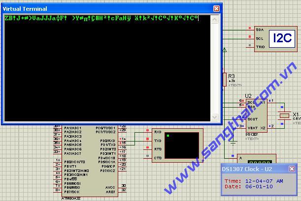
Sơ đồ mạch điện.
- Chương trình mẫu:
Chip type : ATmega32
Program type : Application
Clock frequency : 7.372800 MHz
Memory model : Small
External SRAM size : 0
Data Stack size : 512
*****************************************************/
#include "mega32.h"
#include "AT32_TWI.h"
#include "DS1307.h"
#include "delay.h"
// Standard Input/Output functions
#include
// Declare your global variables here
CLOCK_CFG_TYPE clockcfg;
DATE_TYPE datecfg;
TIME_TYPE timecfg;
HOUR_TYPE hourcfg;
char am_str[] = "AM";
char pm_str[] = "PM";
void main(void)
{
// Declare your local variables here
unsigned char temp_data;
// Input/Output Ports initialization
// Port A initialization
// Func7=In Func6=In Func5=In Func4=In Func3=In Func2=In Func1=In Func0=In
// State7=T State6=T State5=T State4=T State3=T State2=T State1=T State0=T
PORTA=0x00;
DDRA=0x00;
// Port B initialization
// Func7=In Func6=In Func5=In Func4=In Func3=In Func2=In Func1=In Func0=In
// State7=T State6=T State5=T State4=T State3=T State2=T State1=T State0=T
PORTB=0x00;
DDRB=0x00;
// Port C initialization
// Func7=In Func6=In Func5=In Func4=In Func3=In Func2=In Func1=In Func0=In
// State7=T State6=T State5=T State4=T State3=T State2=T State1=T State0=T
PORTC=0x00;
DDRC=0x00;
// Port D initialization
// Func7=In Func6=In Func5=In Func4=In Func3=In Func2=In Func1=In Func0=In
// State7=T State6=T State5=T State4=T State3=T State2=T State1=T State0=T
PORTD=0x00;
DDRD=0x00;
// Timer/Counter 0 initialization
// Clock source: System Clock
// Clock value: Timer 0 Stopped
// Mode: Normal top=FFh
// OC0 output: Disconnected
TCCR0=0x00;
TCNT0=0x00;
OCR0=0x00;
// Timer/Counter 1 initialization
// Clock source: System Clock
// Clock value: Timer 1 Stopped
// Mode: Normal top=FFFFh
// OC1A output: Discon.
// OC1B output: Discon.
// Noise Canceler: Off
// Input Capture on Falling Edge
// Timer 1 Overflow Interrupt: Off
// Input Capture Interrupt: Off
// Compare A Match Interrupt: Off
// Compare B Match Interrupt: Off
TCCR1A=0x00;
TCCR1B=0x00;
TCNT1H=0x00;
TCNT1L=0x00;
ICR1H=0x00;
ICR1L=0x00;
OCR1AH=0x00;
OCR1AL=0x00;
OCR1BH=0x00;
OCR1BL=0x00;
// Timer/Counter 2 initialization
// Clock source: System Clock
// Clock value: Timer 2 Stopped
// Mode: Normal top=FFh
// OC2 output: Disconnected
ASSR=0x00;
TCCR2=0x00;
TCNT2=0x00;
OCR2=0x00;
// External Interrupt(s) initialization
// INT0: Off
// INT1: Off
// INT2: Off
MCUCR=0x00;
MCUCSR=0x00;
// Timer(s)/Counter(s) Interrupt(s) initialization
TIMSK=0x00;
// USART initialization
// Communication Parameters: 8 Data, 1 Stop, No Parity
// USART Receiver: On
// USART Transmitter: On
// USART Mode: Asynchronous
// USART Baud rate: 57600
UCSRA=0x00;
UCSRB=0x18;
UCSRC=0x86;
UBRRH=0x00;
UBRRL=0x07;
// Analog Comparator initialization
// Analog Comparator: Off
// Analog Comparator Input Capture by Timer/Counter 1: Off
ACSR=0x80;
SFIOR=0x00;
/* Init configuration value ------------------------------------------------------------- */
// Clock config - OUT pin state in this case is unused!
clockcfg.clockout = 1; // Enable clock output
clockcfg.clkfreq = FREQ_1Hz; // 1Hz selected
// Date config - set to Jan-06-2010
datecfg.date = 6;
datecfg.day = WEDNESDAY;
datecfg.month = 1;
datecfg.year = 10;
// Time config - set to 12:04:00AM
timecfg.second = 0;
timecfg.minute = 4;
timecfg.hour = 12;
// Hour type config
hourcfg.hour_12_24 = 1; // 12h mode selected
hourcfg.hour_am_pm = 0; // AM
/* Init RTC DS1307 ---------------------------------------------------------------------- */
printf("Date will be set to %d-%d-%d in dd-mm-yy format\n\r", \
datecfg.date, datecfg.month, datecfg.year);
if (hourcfg.hour_12_24){
printf("Time in 12h mode format\n\r");
printf("Time will be set to %d:%d:%d%s in hh:mm:ss(AM/PM) format\n\r", \
timecfg.hour, timecfg.minute, timecfg.second,\
((hourcfg.hour_am_pm) ? pm_str : pm_str));
} else {
printf("Time in 24h mode format\n\r");
printf("Time will be set to %d:%d:%d in hh:mm:ss(AM/PM) format\n\r", \
timecfg.hour, timecfg.minute, timecfg.second);
}
if (DS1307_Init(&clockcfg, &datecfg, &timecfg, &hourcfg) == OK){
printf("Init DS1307 successfully!\n\r");
} else {
printf("Init DS1307 fail!\n\r");
}
/* Read back date value ----------------------------------------------------------------- */
// Reset date data
datecfg.date = 0;
datecfg.day = SUNDAY;
datecfg.month = 0;
datecfg.year = 0;
if (DS1307_GetDate(&datecfg) == OK){
printf("Get date successfully!\n\r");
printf("Current Date: %d-%d-%d\n\r", \
datecfg.date, datecfg.month, datecfg.year);
} else {
printf("Get date fail!\n\r");
}
/* Demo with accessing to General Purpose RAM in DS1307 --------------------------------- */
// Init data to be sent
temp_data = 100;
printf("Now, write to RAM bank 10 with value = %d\n\r", temp_data);
if (DS1307_WriteRAM(10, temp_data) == OK){
printf("Write value to RAM successfully!\n\r");
} else {
printf("Write value to RAM fail!\n\r");
}
/* Read back value from RAM ------------------------------------------------------------- */
// Clear data
temp_data = 0;
printf("Now, read back value from RAM bank 10\n\r");
if (DS1307_ReadRAM(10, &temp_data) == OK){
printf("Read value from RAM successfully! Data = %d\n\r", temp_data);
} else {
printf("Read value from RAM fail!\n\r");
}
// Reset time data
timecfg.second = 0;
timecfg.minute = 0;
timecfg.hour = 0;
// Reset hour type
hourcfg.hour_12_24 = 0;
hourcfg.hour_am_pm = 0;
//Main loop
while (1){
if (DS1307_GetTime(&timecfg, &hourcfg) == OK){
printf("Current Time: %d-%d-%d%s\n\r", \
timecfg.hour, timecfg.minute, timecfg.second,\
((hourcfg.hour_am_pm) ? pm_str : pm_str));
} else {
printf("Get time fail!\n\r");
}
delay_ms(3000);
}
}
22.TWI_I2C_MasterSlaveMode.
- Sơ đồ mạch điện:
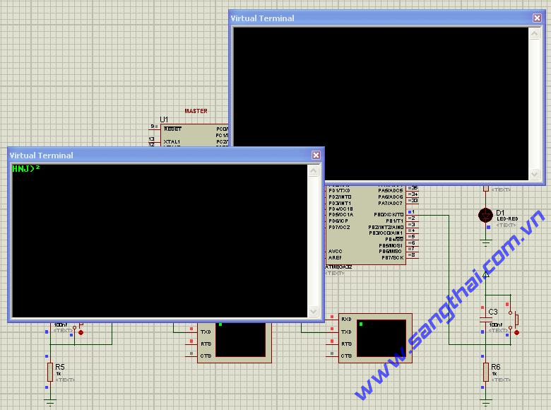
Sơ đồ mạch điện.
- Chương trình mẫu:
- Code master
Chip type : ATmega32
Program type : Application
Clock frequency : 7.372800 MHz
Memory model : Small
External SRAM size : 0
Data Stack size : 512
*****************************************************/
#include "mega32.h"
#include "delay.h"
#include "AT32_TWI.h"
// Standard Input/Output functions
#include
// User's defines
#define BUT PINB.0
#define LED PORTA.0
// Slave address
#define SLAVE_ADDR 0b10100000
// Declare your global variables here
void main(void)
{
// Declare your local variables here
unsigned char data;
// Input/Output Ports initialization
// Port A initialization
// Func7=In Func6=In Func5=In Func4=In Func3=In Func2=In Func1=In Func0=Out
// State7=T State6=T State5=T State4=T State3=T State2=T State1=T State0=0
PORTA=0x00;
DDRA=0x01;
// Port B initialization
// Func7=In Func6=In Func5=In Func4=In Func3=In Func2=In Func1=In Func0=In
// State7=T State6=T State5=T State4=T State3=T State2=T State1=T State0=T
PORTB=0x00;
DDRB=0x00;
// Port C initialization
// Func7=In Func6=In Func5=In Func4=In Func3=In Func2=In Func1=In Func0=In
// State7=T State6=T State5=T State4=T State3=T State2=T State1=T State0=T
PORTC=0x00;
DDRC=0x00;
// Port D initialization
// Func7=In Func6=In Func5=In Func4=In Func3=In Func2=In Func1=In Func0=In
// State7=T State6=T State5=T State4=T State3=T State2=T State1=T State0=T
PORTD=0x00;
DDRD=0x00;
// Timer/Counter 0 initialization
// Clock source: System Clock
// Clock value: Timer 0 Stopped
// Mode: Normal top=FFh
// OC0 output: Disconnected
TCCR0=0x00;
TCNT0=0x00;
OCR0=0x00;
// Timer/Counter 1 initialization
// Clock source: System Clock
// Clock value: Timer 1 Stopped
// Mode: Normal top=FFFFh
// OC1A output: Discon.
// OC1B output: Discon.
// Noise Canceler: Off
// Input Capture on Falling Edge
// Timer 1 Overflow Interrupt: Off
// Input Capture Interrupt: Off
// Compare A Match Interrupt: Off
// Compare B Match Interrupt: Off
TCCR1A=0x00;
TCCR1B=0x00;
TCNT1H=0x00;
TCNT1L=0x00;
ICR1H=0x00;
ICR1L=0x00;
OCR1AH=0x00;
OCR1AL=0x00;
OCR1BH=0x00;
OCR1BL=0x00;
// Timer/Counter 2 initialization
// Clock source: System Clock
// Clock value: Timer 2 Stopped
// Mode: Normal top=FFh
// OC2 output: Disconnected
ASSR=0x00;
TCCR2=0x00;
TCNT2=0x00;
OCR2=0x00;
// External Interrupt(s) initialization
// INT0: Off
// INT1: Off
// INT2: Off
MCUCR=0x00;
MCUCSR=0x00;
// Timer(s)/Counter(s) Interrupt(s) initialization
TIMSK=0x00;
// USART initialization
// Communication Parameters: 8 Data, 1 Stop, No Parity
// USART Receiver: On
// USART Transmitter: On
// USART Mode: Asynchronous
// USART Baud rate: 57600
UCSRA=0x00;
UCSRB=0x18;
UCSRC=0x86;
UBRRH=0x00;
UBRRL=0x07;
// Analog Comparator initialization
// Analog Comparator: Off
// Analog Comparator Input Capture by Timer/Counter 1: Off
ACSR=0x80;
SFIOR=0x00;
TWI_Init();
printf("www.sangthai.com.vn!\n\r");
printf("This is demo for TWI - Master mode\n\r");
while (1){
// Read button state on Master side and send that value to control LED on slave side
data = BUT;
if (TWI_SendData(SLAVE_ADDR,&data,1) == OK){
//printf("Send data OK!\n\r");
} else {
printf("Send data error!\n\r");
}
// Receive data that contains button state on slave side and control LED on master side accordingly
data = 0;
if (TWI_ReceiveData(SLAVE_ADDR,&data,1) == OK){
//printf("Receive data OK!\n\r");
// Drive LED accordingly on master side
LED = data;
} else {
printf("Receive data error!\n\r");
}
// delay a while
delay_ms(100);
}
}
- Code Slave
Chip type : ATmega32
Program type : Application
Clock frequency : 7.372800 MHz
Memory model : Small
External SRAM size : 0
Data Stack size : 512
*****************************************************/
#include "mega32.h"
#include "AT32_TWI_Slave.h"
// Standard Input/Output functions
#include
// User's defines
#define BUT PINB.0
#define LED PORTA.0
// Declare your global variables here
// 2 Wire bus interrupt service routine
interrupt [TWI] void twi_isr(void)
{
unsigned char twcr_data;
// Check status
switch (TWI_STATUS)
{
/* Slave Receive mode ---------------------------------------------------------- */
// Data has been received and ACK has been returned
case SR_PRE_SLA_W_DATA_ACK:
// Get data out of TWDR and drive led
LED = TWDR;
break;
/* Slave Transmit mode ---------------------------------------------------------- */
// Own Slave address + R has been received and ACK has been returned
case SR_SLA_R_ACK:
// Load data to be sent in next data byte
TWDR = BUT;
break;
/* All remaining case ----------------------------------------------------------- */
default:
// Nothing to do here
break;
}
// Clear TWINT flag, skip TWEN, TWEA and TWIE bit enabled
twcr_data |= TWINT | TWEN | TWIE | TWEA;
TWCR = twcr_data;
}
void main(void)
{
// Declare your local variables here
// Input/Output Ports initialization
// Port A initialization
// Func7=In Func6=In Func5=In Func4=In Func3=In Func2=In Func1=In Func0=Out
// State7=T State6=T State5=T State4=T State3=T State2=T State1=T State0=0
PORTA=0x00;
DDRA=0x01;
// Port B initialization
// Func7=In Func6=In Func5=In Func4=In Func3=In Func2=In Func1=In Func0=In
// State7=T State6=T State5=T State4=T State3=T State2=T State1=T State0=T
PORTB=0x00;
DDRB=0x00;
// Port C initialization
// Func7=In Func6=In Func5=In Func4=In Func3=In Func2=In Func1=In Func0=In
// State7=T State6=T State5=T State4=T State3=T State2=T State1=T State0=T
PORTC=0x00;
DDRC=0x00;
// Port D initialization
// Func7=In Func6=In Func5=In Func4=In Func3=In Func2=In Func1=In Func0=In
// State7=T State6=T State5=T State4=T State3=T State2=T State1=T State0=T
PORTD=0x00;
DDRD=0x00;
// Timer/Counter 0 initialization
// Clock source: System Clock
// Clock value: Timer 0 Stopped
// Mode: Normal top=FFh
// OC0 output: Disconnected
TCCR0=0x00;
TCNT0=0x00;
OCR0=0x00;
// Timer/Counter 1 initialization
// Clock source: System Clock
// Clock value: Timer 1 Stopped
// Mode: Normal top=FFFFh
// OC1A output: Discon.
// OC1B output: Discon.
// Noise Canceler: Off
// Input Capture on Falling Edge
// Timer 1 Overflow Interrupt: Off
// Input Capture Interrupt: Off
// Compare A Match Interrupt: Off
// Compare B Match Interrupt: Off
TCCR1A=0x00;
TCCR1B=0x00;
TCNT1H=0x00;
TCNT1L=0x00;
ICR1H=0x00;
ICR1L=0x00;
OCR1AH=0x00;
OCR1AL=0x00;
OCR1BH=0x00;
OCR1BL=0x00;
// Timer/Counter 2 initialization
// Clock source: System Clock
// Clock value: Timer 2 Stopped
// Mode: Normal top=FFh
// OC2 output: Disconnected
ASSR=0x00;
TCCR2=0x00;
TCNT2=0x00;
OCR2=0x00;
// External Interrupt(s) initialization
// INT0: Off
// INT1: Off
// INT2: Off
MCUCR=0x00;
MCUCSR=0x00;
// Timer(s)/Counter(s) Interrupt(s) initialization
TIMSK=0x00;
// USART initialization
// Communication Parameters: 8 Data, 1 Stop, No Parity
// USART Receiver: On
// USART Transmitter: On
// USART Mode: Asynchronous
// USART Baud rate: 57600
UCSRA=0x00;
UCSRB=0x18;
UCSRC=0x86;
UBRRH=0x00;
UBRRL=0x07;
// Analog Comparator initialization
// Analog Comparator: Off
// Analog Comparator Input Capture by Timer/Counter 1: Off
ACSR=0x80;
SFIOR=0x00;
// 2 Wire Bus initialization
// Generate Acknowledge Pulse: On
// 2 Wire Bus Slave Address: 50h
// General Call Recognition: On
// Bit Rate: 102.400 kHz
TWSR=0x00;
TWBR=0x1C;
TWAR=0xA1;
TWCR=0x45;
#asm("sei")
while (1);
}
23.SPI_HC595.
- Sơ đồ mạch điện:
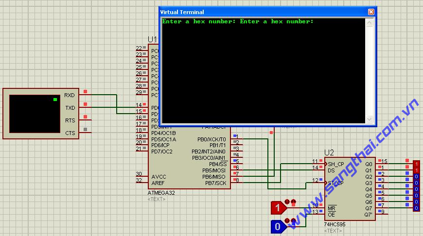
Sơ đồ mạch điện.
- Chương trình mẫu:
Chip type : ATmega32
Program type : Application
Clock frequency : 7.372800 MHz
Memory model : Small
External SRAM size : 0
Data Stack size : 512
*****************************************************/
#include "mega32.h"
// Standard Input/Output functions
#include "spi.h"
// SPI functions
#include "stdio.h"
// User's defines
#define LATCH PORTB.0
// Declare your global variables here
void main(void)
{
// Declare your local variables here
unsigned char input_hex;
// Input/Output Ports initialization
// Port A initialization
// Func7=In Func6=In Func5=In Func4=In Func3=In Func2=In Func1=In Func0=In
// State7=T State6=T State5=T State4=T State3=T State2=T State1=T State0=T
PORTA=0x00;
DDRA=0x00;
// Port B initialization
// Func7=Out Func6=Out Func5=Out Func4=Out Func3=In Func2=In Func1=In Func0=Out
// State7=0 State6=0 State5=0 State4=0 State3=T State2=T State1=T State0=0
PORTB=0x00;
DDRB=0xF1;
// Port C initialization
// Func7=In Func6=In Func5=In Func4=In Func3=In Func2=In Func1=In Func0=In
// State7=T State6=T State5=T State4=T State3=T State2=T State1=T State0=T
PORTC=0x00;
DDRC=0x00;
// Port D initialization
// Func7=In Func6=In Func5=In Func4=In Func3=In Func2=In Func1=In Func0=In
// State7=T State6=T State5=T State4=T State3=T State2=T State1=T State0=T
PORTD=0x00;
DDRD=0x00;
// Timer/Counter 0 initialization
// Clock source: System Clock
// Clock value: Timer 0 Stopped
// Mode: Normal top=FFh
// OC0 output: Disconnected
TCCR0=0x00;
TCNT0=0x00;
OCR0=0x00;
// Timer/Counter 1 initialization
// Clock source: System Clock
// Clock value: Timer 1 Stopped
// Mode: Normal top=FFFFh
// OC1A output: Discon.
// OC1B output: Discon.
// Noise Canceler: Off
// Input Capture on Falling Edge
// Timer 1 Overflow Interrupt: Off
// Input Capture Interrupt: Off
// Compare A Match Interrupt: Off
// Compare B Match Interrupt: Off
TCCR1A=0x00;
TCCR1B=0x00;
TCNT1H=0x00;
TCNT1L=0x00;
ICR1H=0x00;
ICR1L=0x00;
OCR1AH=0x00;
OCR1AL=0x00;
OCR1BH=0x00;
OCR1BL=0x00;
// Timer/Counter 2 initialization
// Clock source: System Clock
// Clock value: Timer 2 Stopped
// Mode: Normal top=FFh
// OC2 output: Disconnected
ASSR=0x00;
TCCR2=0x00;
TCNT2=0x00;
OCR2=0x00;
// External Interrupt(s) initialization
// INT0: Off
// INT1: Off
// INT2: Off
MCUCR=0x00;
MCUCSR=0x00;
// Timer(s)/Counter(s) Interrupt(s) initialization
TIMSK=0x00;
// USART initialization
// Communication Parameters: 8 Data, 1 Stop, No Parity
// USART Receiver: On
// USART Transmitter: On
// USART Mode: Asynchronous
// USART Baud rate: 9600
UCSRA=0x00;
UCSRB=0x18;
UCSRC=0x86;
UBRRH=0x00;
UBRRL=0x2F;
// Analog Comparator initialization
// Analog Comparator: Off
// Analog Comparator Input Capture by Timer/Counter 1: Off
ACSR=0x80;
SFIOR=0x00;
// SPI initialization
// SPI Type: Master
// SPI Clock Rate: 1843.200 kHz
// SPI Clock Phase: Cycle Start
// SPI Clock Polarity: High
// SPI Data Order: MSB First
SPCR=0x5C;
SPSR=0x00;
LATCH = 0;
while (1){
printf("Enter a hex number: ");
scanf("%x",&input_hex);
spi(input_hex);
LATCH = 1;
LATCH = 0;
}
}
24.SPI_Master_Slave
- Sơ đồ mạch điện:
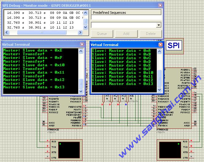
Sơ đồ mạch điện.
-
- Chương trình mẫu:
- Code master
Chip type : ATmega32
Program type : Application
Clock frequency : 7.372800 MHz
Memory model : Small
External SRAM size : 0
Data Stack size : 512
*****************************************************/
#include "mega32.h"
#include"delay.h"
// Standard Input/Output functions
#include "stdio.h"
// SPI functions
#include "spi.h"
// SS
#define SS PORTB.0
#define EN 0
#define DIS 1
// Declare your global variables here
unsigned char master_data = 0;
unsigned char slave_data = 0;
void main(void)
{
// Declare your local variables here
unsigned char i;
// Input/Output Ports initialization
// Port A initialization
// Func7=In Func6=In Func5=In Func4=In Func3=In Func2=In Func1=In Func0=In
// State7=T State6=T State5=T State4=T State3=T State2=T State1=T State0=T
PORTA=0x00;
DDRA=0x00;
// Port B initialization
// Func7=Out Func6=In Func5=Out Func4=Out Func3=In Func2=In Func1=In Func0=In
// State7=0 State6=T State5=0 State4=0 State3=T State2=T State1=T State0=T
PORTB=0x00;
DDRB=0xB1;
// Port C initialization
// Func7=In Func6=In Func5=In Func4=In Func3=In Func2=In Func1=In Func0=In
// State7=T State6=T State5=T State4=T State3=T State2=T State1=T State0=T
PORTC=0x00;
DDRC=0x00;
// Port D initialization
// Func7=In Func6=In Func5=In Func4=In Func3=In Func2=In Func1=In Func0=In
// State7=T State6=T State5=T State4=T State3=T State2=T State1=T State0=T
PORTD=0x00;
DDRD=0x00;
// Timer/Counter 0 initialization
// Clock source: System Clock
// Clock value: Timer 0 Stopped
// Mode: Normal top=FFh
// OC0 output: Disconnected
TCCR0=0x00;
TCNT0=0x00;
OCR0=0x00;
// Timer/Counter 1 initialization
// Clock source: System Clock
// Clock value: Timer 1 Stopped
// Mode: Normal top=FFFFh
// OC1A output: Discon.
// OC1B output: Discon.
// Noise Canceler: Off
// Input Capture on Falling Edge
// Timer 1 Overflow Interrupt: Off
// Input Capture Interrupt: Off
// Compare A Match Interrupt: Off
// Compare B Match Interrupt: Off
TCCR1A=0x00;
TCCR1B=0x00;
TCNT1H=0x00;
TCNT1L=0x00;
ICR1H=0x00;
ICR1L=0x00;
OCR1AH=0x00;
OCR1AL=0x00;
OCR1BH=0x00;
OCR1BL=0x00;
// Timer/Counter 2 initialization
// Clock source: System Clock
// Clock value: Timer 2 Stopped
// Mode: Normal top=FFh
// OC2 output: Disconnected
ASSR=0x00;
TCCR2=0x00;
TCNT2=0x00;
OCR2=0x00;
// External Interrupt(s) initialization
// INT0: Off
// INT1: Off
// INT2: Off
MCUCR=0x00;
MCUCSR=0x00;
// Timer(s)/Counter(s) Interrupt(s) initialization
TIMSK=0x00;
// USART initialization
// Communication Parameters: 8 Data, 1 Stop, No Parity
// USART Receiver: On
// USART Transmitter: On
// USART Mode: Asynchronous
// USART Baud rate: 9600
UCSRA=0x00;
UCSRB=0x18;
UCSRC=0x86;
UBRRH=0x00;
UBRRL=0x2F;
// Analog Comparator initialization
// Analog Comparator: Off
// Analog Comparator Input Capture by Timer/Counter 1: Off
ACSR=0x80;
SFIOR=0x00;
// SPI initialization
// SPI Type: Master
// SPI Clock Rate: 1843.200 kHz
// SPI Clock Phase: Cycle Half
// SPI Clock Polarity: Low
// SPI Data Order: MSB First
SPCR=0x50;
SPSR=0x00;
SS = DIS;
while (1){
SS = EN;
printf("Master: Transfer!\n\r");
slave_data = spi(master_data++);
SS = DIS;
printf("Master: Slave data = 0x%X\n\r", slave_data);
delay_ms(2000);
}
}
- Code Slave
Chip type : ATmega32
Program type : Application
Clock frequency : 7.372800 MHz
Memory model : Small
External SRAM size : 0
Data Stack size : 512
#include "mega32.h"
#include "delay.h"
// Standard Input/Output functions
#include "spi.h"
unsigned char master_data = 0;
unsigned char slave_data = 0;
// SPI interrupt service routine
interrupt [SPI_STC] void spi_isr(void)
{
master_data = SPDR;
SPDR = slave_data++;
// Place your code here
printf("Slave: Master data = 0x%X\n\r", master_data);
}
// Declare your global variables here
void main(void)
{
// Declare your local variables here
// Input/Output Ports initialization
// Port A initialization
// Func7=In Func6=In Func5=In Func4=In Func3=In Func2=In Func1=In Func0=In
// State7=T State6=T State5=T State4=T State3=T State2=T State1=T State0=T
PORTA=0x00;
DDRA=0x00;
// Port B initialization
// Func7=In Func6=Out Func5=In Func4=In Func3=In Func2=In Func1=In Func0=In
// State7=T State6=0 State5=T State4=T State3=T State2=T State1=T State0=T
PORTB=0x00;
DDRB=0x40;
// Port C initialization
// Func7=In Func6=In Func5=In Func4=In Func3=In Func2=In Func1=In Func0=In
// State7=T State6=T State5=T State4=T State3=T State2=T State1=T State0=T
PORTC=0x00;
DDRC=0x00;
// Port D initialization
// Func7=In Func6=In Func5=In Func4=In Func3=In Func2=In Func1=In Func0=In
// State7=T State6=T State5=T State4=T State3=T State2=T State1=T State0=T
PORTD=0x00;
DDRD=0x00;
// Timer/Counter 0 initialization
// Clock source: System Clock
// Clock value: Timer 0 Stopped
// Mode: Normal top=FFh
// OC0 output: Disconnected
TCCR0=0x00;
TCNT0=0x00;
OCR0=0x00;
// Timer/Counter 1 initialization
// Clock source: System Clock
// Clock value: Timer 1 Stopped
// Mode: Normal top=FFFFh
// OC1A output: Discon.
// OC1B output: Discon.
// Noise Canceler: Off
// Input Capture on Falling Edge
// Timer 1 Overflow Interrupt: Off
// Input Capture Interrupt: Off
// Compare A Match Interrupt: Off
// Compare B Match Interrupt: Off
TCCR1A=0x00;
TCCR1B=0x00;
TCNT1H=0x00;
TCNT1L=0x00;
ICR1H=0x00;
ICR1L=0x00;
OCR1AH=0x00;
OCR1AL=0x00;
OCR1BH=0x00;
OCR1BL=0x00;
// Timer/Counter 2 initialization
// Clock source: System Clock
// Clock value: Timer 2 Stopped
// Mode: Normal top=FFh
// OC2 output: Disconnected
ASSR=0x00;
TCCR2=0x00;
TCNT2=0x00;
OCR2=0x00;
// External Interrupt(s) initialization
// INT0: Off
// INT1: Off
// INT2: Off
MCUCR=0x00;
MCUCSR=0x00;
// Timer(s)/Counter(s) Interrupt(s) initialization
TIMSK=0x00;
// USART initialization
// Communication Parameters: 8 Data, 1 Stop, No Parity
// USART Receiver: On
// USART Transmitter: On
// USART Mode: Asynchronous
// USART Baud rate: 9600
UCSRA=0x00;
UCSRB=0x18;
UCSRC=0x86;
UBRRH=0x00;
UBRRL=0x2F;
// Analog Comparator initialization
// Analog Comparator: Off
// Analog Comparator Input Capture by Timer/Counter 1: Off
ACSR=0x80;
SFIOR=0x00;
// SPI initialization
// SPI Type: Slave
// SPI Clock Rate: 1843.200 kHz
// SPI Clock Phase: Cycle Half
// SPI Clock Polarity: Low
// SPI Data Order: MSB First
SPCR=0xC0;
SPSR=0x00;
// Clear the SPI interrupt flag
#asm
in r30,spsr
in r30,spdr
#endasm
// Global enable interrupts
#asm("sei")
SPDR = slave_data++;
while (1);
}
Nguồn: sangthai.com
Các tin khác
- Giới thiệu về đèn năng lượng mặt trời
- ĐÈN NĂNG LƯỢNG MẶT TRỜI
- Giới thiệu về đèn năng lượng mặt trời
- ĐÈN NĂNG LƯỢNG MẶT TRỜI
- ĐÈN LED NHÀ XƯỞNG
- ĐÈN NĂNG LƯỢNG MẶT TRỜI
- Giới thiệu về đèn năng lượng mặt trời
- ĐẠI LÝ PHÂN PHỐI ĐÈN NLMT - Giá Sỉ
- Giới thiệu về đèn năng lượng mặt trời
- ĐÈN NĂNG LƯỢNG MẶT TRỜI
- Giới thiệu về đèn năng lượng mặt trời
- ĐÈN NĂNG LƯỢNG MẶT TRỜI
- Giới thiệu về đèn năng lượng mặt trời
- ĐÈN NĂNG LƯỢNG MẶT TRỜI
- ĐÈN LED NHÀ XƯỞNG
- ĐẠI LÝ PHÂN PHỐI ĐÈN NLMT - Giá Sỉ
- Giới thiệu về đèn năng lượng mặt trời
- ĐÈN NĂNG LƯỢNG MẶT TRỜI
- Thi công điện nhà xưởng tại bình dương tháng 4
- Thi công điện nhà xưởng tại bình dương tháng 4

Phản hồi (0)